JEE MainPhysicsAlternating CurrentNumerical+4 / −1
As shown in the figure an inductor of inductance 200 mH is connected to an AC source of emf 220 V and frequency 50 Hz. The instantaneous voltage of the source is 0 V when the peak value of current is A. The value of is . 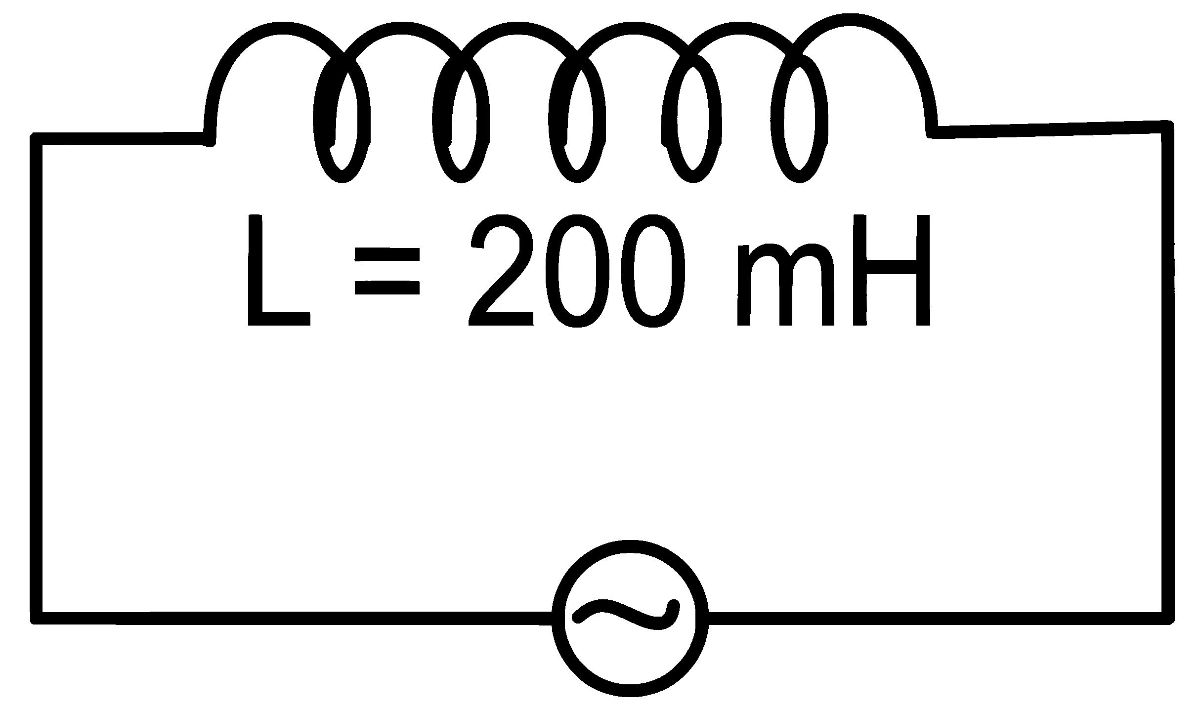
Numerical answer
More from Alternating Current
- Given below are two statements : Statement I : The reactance of an ac circuit is zero. It is possible that the circuit contains a capacitor and an inductor. Statement II : In ac circuit, the average power delivered by the source never…2022 · MCQ
- To increase the resonant frequency in series LCR circuit,2022 · MCQ
- When you walk through a metal detector carrying a metal object in your pocket, it raises an alarm. This phenomenon works on :2022 · MCQ
- Match List-I with List-II. Choose the correct answer from the options given below : Includes table2022 · MCQ
- If wattless current flows in the AC circuit, then the circuit is :2022 · MCQ
- A sinusoidal voltage V(t) = 210 sin 3000 t volt is applied to a series LCR circuit in which L = 10 mH, C = 25 F and R = 100 . The phase difference () between the applied voltage and resultant current will be :2022 · MCQ
- In a series LCR circuit, the inductance, capacitance and resistance are L = 100 mH, C = 100 F and R = 10 respectively. They are connected to an AC source of voltage 220 V and frequency of 50 Hz. The approximate value of… Includes diagram2022 · Numerical
- In a series circuit and power factor of the circuit is . When capacitor with capacitance such that is put in series, the power factor becomes . The ratio is:2022 · MCQ